本課程是使用 Arduino IDE 實現 ESP32 Deep Sleep 深度睡眠模式的完整指南。我們將展示如何讓 ESP32 進入深度睡眠,並了解喚醒它的不同模式:定時器喚醒、觸摸喚醒和外部喚醒。本課程提供了程式碼解釋和原理圖的實際範例。
本課程分為下列4個部分來說明:
- 導入深度睡眠模式(Deep Sleep Mode)
- 定時器喚醒(Timer Wake Up)
- 觸摸喚醒(Touch Wake Up)
- 從外部喚醒(External Wake Up)
文章目錄標題
導入深度睡眠模式
ESP32可以在不同的電源模式之間切換:
- Active mode
- Modem Sleep mode
- Light Sleep mode
- Deep Sleep mode
- Hibernation mode
您可以從 ESP32 Espressif數據表中比較下表中的五種不同模式。

ESP32 Espressif數據表還提供了一個比較不同功耗模式的功耗的表格。
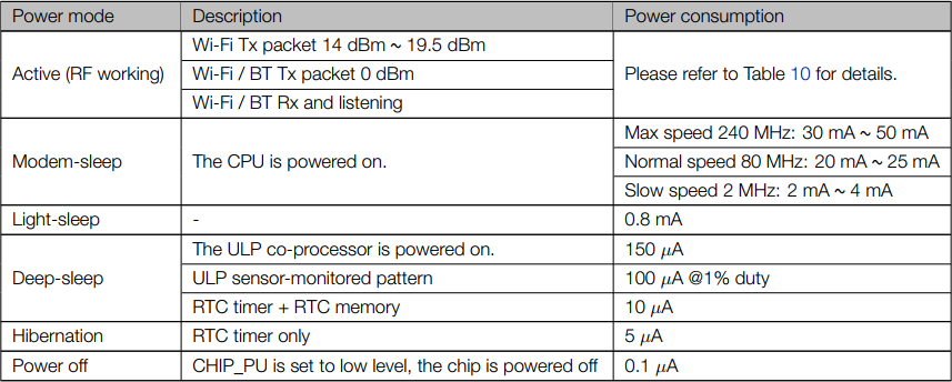
這裡還有表 10來比較活動模式下的功耗:

為什麼選擇深度睡眠模式?
ESP32 在使用電池在活動模式下運行並不理想,因為電池的電量會很快耗盡。
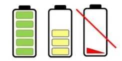
如果您將 ESP32 設定成深度睡眠模式,這樣ESP32就會減少功耗,並且您的電池將持續執行更長運行時間。
讓您的 ESP32 處於深度睡眠模式意味著減少運行時消耗更多功率的活動,而只需要留下足夠的活動以在發生對應的事件來喚醒處理器。
在深度睡眠模式下,CPU 或 Wi-Fi 活動都不會發生,但超低功耗 (ULP) 協處理器仍然可以開機。
當 ESP32 處於深度睡眠模式時,RTC 記憶體也保持通電狀態,因此我們可以為 ULP 協處理器編寫程序並將其存儲在 RTC 記憶體中,來訪問外圍設備、內部定時器和內部感測器。
如果您需要通過外部事件、定時器或兩者喚醒主 CPU,同時保持最低功耗,這種操作模式很有用。
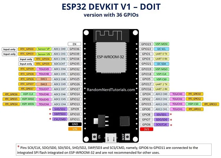
RTC_GPIO 引腳
在深度睡眠期間,ULP 協處理器可以使用一些 ESP32 引腳,即 RTC_GPIO 引腳和觸控引腳。ESP32 數據表提供了一個標識 RTC_GPIO 引腳的表格。您可以在第 7 頁找到該表格。
您可以使用該表作為參考,或查看以下引腳分配來定位不同的 RTC_GPIO 引腳。RTC_GPIO 引腳以橙色矩形框突出顯示。
喚醒電源
在 ESP32 設置於深度睡眠模式後,有下列幾種喚醒方式:
- 您可以使用計時器,使用預定義的時間設定來喚醒您的 ESP32
- 您可以使用觸摸引腳
- 您可以使用兩種外部喚醒方式
- 您可以使用ULP 協處理器來喚醒 – 這裡不對此進行介紹
寫一個深度睡眠草稿圖
要編寫一個草稿圖來使您的 ESP32 進入深度睡眠模式,然後將其喚醒,您需要記住:
- 首先,您需要配置喚醒源。意思是配置將喚醒 ESP32 的內容。您可以使用一個或組合多個喚醒源。
- 您可以決定在深度睡眠期間關閉或繼續使用哪些外圍設備。但是,預設情況下,ESP32 會自動關閉您定義的喚醒源不需要的外圍設備。
- 最後,您使用esp_deep_sleep_start()使您的 ESP32 進入深度睡眠模式的功能。
定時器喚醒
ESP32 可以進入深度睡眠模式,然後在預定義的時間段喚醒。如果您正在運行需要時間戳或日常任務的項目,同時保持低功耗,則此功能特別有用。

ESP32 RTC 控制器有一個內置定時器,您可以使用它在預定義的時間後喚醒 ESP32。
啟用定時器喚醒
讓 ESP32 在預定義的時間後喚醒非常簡單。在 Arduino IDE 中,您只需在以下函數中指定睡眠時間(以微秒為單位):
esp_sleep_enable_timer_wakeup(time_in_us)
程式碼
讓我們使用程式庫中的範例來看看它是如何工作的。打開您的 Arduino IDE,然後轉到檔案 > 範例 > ESP32 > Deep Sleep,然後打開TimerWakeUp草稿圖。
/*
Simple Deep Sleep with Timer Wake Up
=====================================
ESP32 offers a deep sleep mode for effective power
saving as power is an important factor for IoT
applications. In this mode CPUs, most of the RAM,
and all the digital peripherals which are clocked
from APB_CLK are powered off. The only parts of
the chip which can still be powered on are:
RTC controller, RTC peripherals ,and RTC memories

This code displays the most basic deep sleep with
a timer to wake it up and how to store data in
RTC memory to use it over reboots

This code is under Public Domain License.

Author:
Pranav Cherukupalli
*/

#define uS_TO_S_FACTOR 1000000ULL  /* Conversion factor for micro seconds to seconds */
#define TIME_TO_SLEEP  5        /* Time ESP32 will go to sleep (in seconds) */

RTC_DATA_ATTR int bootCount = 0;

/*
Method to print the reason by which ESP32
has been awaken from sleep
*/
void print_wakeup_reason(){
  esp_sleep_wakeup_cause_t wakeup_reason;

  wakeup_reason = esp_sleep_get_wakeup_cause();

  switch(wakeup_reason)
  {
    case ESP_SLEEP_WAKEUP_EXT0 : Serial.println("Wakeup caused by external signal using RTC_IO"); break;
    case ESP_SLEEP_WAKEUP_EXT1 : Serial.println("Wakeup caused by external signal using RTC_CNTL"); break;
    case ESP_SLEEP_WAKEUP_TIMER : Serial.println("Wakeup caused by timer"); break;
    case ESP_SLEEP_WAKEUP_TOUCHPAD : Serial.println("Wakeup caused by touchpad"); break;
    case ESP_SLEEP_WAKEUP_ULP : Serial.println("Wakeup caused by ULP program"); break;
    default : Serial.printf("Wakeup was not caused by deep sleep: %d\n",wakeup_reason); break;
  }
}

void setup(){
  Serial.begin(115200);
  delay(1000); //Take some time to open up the Serial Monitor

  //Increment boot number and print it every reboot
  ++bootCount;
  Serial.println("Boot number: " + String(bootCount));

  //Print the wakeup reason for ESP32
  print_wakeup_reason();

  /*
  First we configure the wake up source
  We set our ESP32 to wake up every 5 seconds
  */
  esp_sleep_enable_timer_wakeup(TIME_TO_SLEEP * uS_TO_S_FACTOR);
  Serial.println("Setup ESP32 to sleep for every " + String(TIME_TO_SLEEP) +
  " Seconds");

  /*
  Next we decide what all peripherals to shut down/keep on
  By default, ESP32 will automatically power down the peripherals
  not needed by the wakeup source, but if you want to be a poweruser
  this is for you. Read in detail at the API docs
  http://esp-idf.readthedocs.io/en/latest/api-reference/system/deep_sleep.html
  Left the line commented as an example of how to configure peripherals.
  The line below turns off all RTC peripherals in deep sleep.
  */
  //esp_deep_sleep_pd_config(ESP_PD_DOMAIN_RTC_PERIPH, ESP_PD_OPTION_OFF);
  //Serial.println("Configured all RTC Peripherals to be powered down in sleep");

  /*
  Now that we have setup a wake cause and if needed setup the
  peripherals state in deep sleep, we can now start going to
  deep sleep.
  In the case that no wake up sources were provided but deep
  sleep was started, it will sleep forever unless hardware
  reset occurs.
  */
  Serial.println("Going to sleep now");
  Serial.flush();
  esp_deep_sleep_start();
  Serial.println("This will never be printed");
}

void loop(){
  //This is not going to be called
}
讓我們看一下這段程式碼。第一條評論描述了在深度睡眠期間通過定時器喚醒關閉的內容。
在這種模式下,CPU、大部分 RAM
和所有由 APB_CLK 提供時鐘的數字外設都
將斷電。晶片中唯一
仍可以上電的部分是:
RTC 控制器、RTC 外設和 RTC 存儲器
當您使用定時器喚醒時,將被上電的部分是 RTC 控制器、RTC 外設和 RTC 存儲器。
定義睡眠時間
前兩行程式碼定義了 ESP32 休眠的時間段。
#define uS_TO_S_FACTOR 1000000 /* Conversion factor for micro seconds to seconds */
#define TIME_TO_SLEEP 5 /* Time ESP32 will go to sleep (in seconds) */
此範例使用從微秒到秒的轉換因子,以便您可以在 TIME_TO_SLEEP 以秒為單位的變量。在這種情況下,該範例將使 ESP32 進入深度睡眠模式 5 秒。
將數據保存在 RTC 存儲器上
使用 ESP32,您可以將數據儲存在 RTC 存儲器中。ESP32 在 RTC 部分有 8kB SRAM,稱為 RTC 快閃存儲器。此處保存的數據在深度睡眠期間不會被刪除。但是,當您按下reset按鈕(ESP32 板上標記為 EN 的按鈕)時,它會被刪除。
要將數據保存在 RTC 記憶體中,您只需新增RTC_DATA_ATTR在變量定義之前。該範例保存引導計數RTC 記憶體上的變量。該變量將計算 ESP32 從深度睡眠中喚醒的次數。
RTC_DATA_ATTR int bootCount = 0;
喚醒原因
然後,程式碼定義print_wakeup_reason()函數,印出 ESP32 從睡眠中喚醒的原因。
void print_wakeup_reason(){
  esp_sleep_wakeup_cause_t wakeup_reason;
  wakeup_reason = esp_sleep_get_wakeup_cause();
  switch(wakeup_reason){
    case ESP_SLEEP_WAKEUP_EXT0 : Serial.println("Wakeup caused by external signal using RTC_IO"); break;
    case ESP_SLEEP_WAKEUP_EXT1 : Serial.println("Wakeup caused by external signal using RTC_CNTL"); break;
    case ESP_SLEEP_WAKEUP_TIMER : Serial.println("Wakeup caused by timer"); break;
    case ESP_SLEEP_WAKEUP_TOUCHPAD : Serial.println("Wakeup caused by touchpad"); break;
    case ESP_SLEEP_WAKEUP_ULP : Serial.println("Wakeup caused by ULP program"); break;
    default : Serial.printf("Wakeup was not caused by deep sleep: %d\n",wakeup_reason); break;
  }
}
Setup()
在setup()裡是您應該放置程式碼的地方。在深眠中,草稿圖永遠不會跑loop()函數。所以,你需要把所有的草稿圖程式碼都寫在setup()裡.
此範例首先以 115200 的鮑率初始化串行通信。
Serial.begin(115200);
然後,引導計數每次重新啟動時變量都會增加1,並且該數字會列印在序列埠監控視窗中。
Serial.println(“Boot number: “ + String(bootCount));
然後,程式碼調用print_wakeup_reason()函數,但您可以調用任何要執行所需任務的函數。例如,您可能希望每天喚醒 ESP32 一次以從感測器讀取值。
接下來,程式碼使用以下函數定義喚醒源:
esp_sleep_enable_timer_wakeup(time_in_us)
正如我們之前所見,此函數接受以微秒為單位的睡眠時間作為參數。
在這個例子中,我們有以下內容:
esp_sleep_enable_timer_wakeup(TIME_TO_SLEEP * uS_TO_S_FACTOR);
然後,在執行完所有任務後,esp 通過調用以下函數進入睡眠狀態:
esp_deep_sleep_start()
loop()
loop()函數部分內程式碼是空的,因為 ESP32 將在到達這部分程式碼之前進入睡眠狀態。所以,你需要把你所有的草稿圖程式碼都寫在setup()內.
將範例草稿圖上傳到您的 ESP32。確保您選擇了正確的開發板和 COM 端口。
測試定時器喚醒
以 115200 的鮑率打開序列埠監控視窗。

每 5 秒,ESP 喚醒,在序列埠監控視窗上列印一條訊息,然後再次進入深度睡眠。
每次 ESP 喚醒引導計數變量增加。它還列印喚醒原因,如下圖所示。
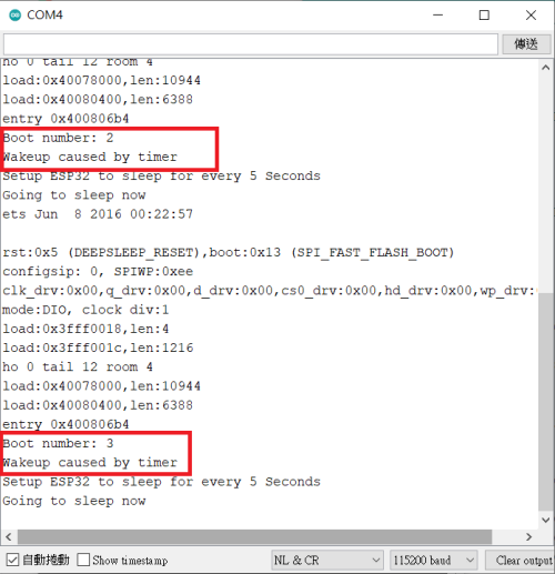
但是,請注意,如果您按下 ESP32 板上的 EN 按鈕,它會將引導計數再次重置為 1。
您可以自己修改第三方提供的範例,而不是只是列印計數增加的訊息,您可以讓您 ESP 執行任何其他任務。定時器喚醒對於使用 ESP32 執行定期任務(如日常任務)很有用,且不會消耗太多電量。
觸摸喚醒
您可以使用觸摸引腳將 ESP32 從深度睡眠中喚醒。本節展示如何使用 Arduino IDE 做到這一點。

啟用觸控喚醒
使用觸摸引腳使 ESP32 喚醒很簡單。在 Arduino IDE 中,您需要使用以下函數:
esp_sleep_enable_touchpad_wakeup()程式碼
讓我們使用程式庫中的範例來看看它是如何工作的。打開您的 Arduino IDE,然後轉到檔案 > 範例 > ESP32 > Deep Sleep,然後打開TouchWakeUp草稿圖。
/*
Deep Sleep with Touch Wake Up
=====================================
This code displays how to use deep sleep with
a touch as a wake up source and how to store data in
RTC memory to use it over reboots

This code is under Public Domain License.

Author:
Pranav Cherukupalli <cherukupallip@gmail.com>
*/

#define Threshold 40 /* Greater the value, more the sensitivity */

RTC_DATA_ATTR int bootCount = 0;
touch_pad_t touchPin;
/*
Method to print the reason by which ESP32
has been awaken from sleep
*/
void print_wakeup_reason(){
  esp_sleep_wakeup_cause_t wakeup_reason;

  wakeup_reason = esp_sleep_get_wakeup_cause();

  switch(wakeup_reason)
  {
    case ESP_SLEEP_WAKEUP_EXT0 : Serial.println("Wakeup caused by external signal using RTC_IO"); break;
    case ESP_SLEEP_WAKEUP_EXT1 : Serial.println("Wakeup caused by external signal using RTC_CNTL"); break;
    case ESP_SLEEP_WAKEUP_TIMER : Serial.println("Wakeup caused by timer"); break;
    case ESP_SLEEP_WAKEUP_TOUCHPAD : Serial.println("Wakeup caused by touchpad"); break;
    case ESP_SLEEP_WAKEUP_ULP : Serial.println("Wakeup caused by ULP program"); break;
    default : Serial.printf("Wakeup was not caused by deep sleep: %d\n",wakeup_reason); break;
  }
}

/*
Method to print the touchpad by which ESP32
has been awaken from sleep
*/
void print_wakeup_touchpad(){
  touchPin = esp_sleep_get_touchpad_wakeup_status();

  switch(touchPin)
  {
    case 0  : Serial.println("Touch detected on GPIO 4"); break;
    case 1  : Serial.println("Touch detected on GPIO 0"); break;
    case 2  : Serial.println("Touch detected on GPIO 2"); break;
    case 3  : Serial.println("Touch detected on GPIO 15"); break;
    case 4  : Serial.println("Touch detected on GPIO 13"); break;
    case 5  : Serial.println("Touch detected on GPIO 12"); break;
    case 6  : Serial.println("Touch detected on GPIO 14"); break;
    case 7  : Serial.println("Touch detected on GPIO 27"); break;
    case 8  : Serial.println("Touch detected on GPIO 33"); break;
    case 9  : Serial.println("Touch detected on GPIO 32"); break;
    default : Serial.println("Wakeup not by touchpad"); break;
  }
}

void callback(){
  //placeholder callback function
}

void setup(){
  Serial.begin(115200);
  delay(1000); //Take some time to open up the Serial Monitor

  //Increment boot number and print it every reboot
  ++bootCount;
  Serial.println("Boot number: " + String(bootCount));

  //Print the wakeup reason for ESP32 and touchpad too
  print_wakeup_reason();
  print_wakeup_touchpad();

  //Setup interrupt on Touch Pad 3 (GPIO15)
  touchAttachInterrupt(T3, callback, Threshold);

  //Configure Touchpad as wakeup source
  esp_sleep_enable_touchpad_wakeup();

  //Go to sleep now
  Serial.println("Going to sleep now");
  esp_deep_sleep_start();
  Serial.println("This will never be printed");
}

void loop(){
  //This will never be reached
}
設置閾值
您需要做的第一件事是為觸摸引腳設置閾值。在這種情況下,我們設置臨界點到 40。您可能需要根據您的項目更改閾值。
#define Threshold 40當您觸摸觸摸感應 GPIO 時,感測器讀取的值會減小。因此,您可以設置一個閾值,以便在檢測到觸摸時發生某些事情。
這裡設置的閾值意味著當觸摸感應GPIO讀取的值低於40時,ESP32應該被喚醒。您可以根據所需的靈敏度調整該值。
附加中斷
您需要將中斷附加到觸感引腳。當在指定的 GPIO 上檢測到觸摸時,將執行回調函數。例如,看一下以下行:
//Setup interrupt on Touch Pad 3 (GPIO15)
 touchAttachInterrupt(T3, callback, Threshold);
當在 T3 上讀取的值 (通用輸入輸出接口 15) 低於上設置的值臨界點變量,ESP32 喚醒和callback功能被執行。
這callback()僅當 ESP32 處於喚醒狀態時才會執行該函數。
- 如果 ESP32 處於睡眠狀態並且您觸摸 T3,ESP 將喚醒 –callback()如果只是按下並釋放觸摸針,功能將不會執行;
- 如果 ESP32 處於喚醒狀態並且您觸摸 T3,則會執行回調函數。所以,如果你想執行callback()喚醒 ESP32 時,您需要按住該引腳上的觸摸一段時間,直到該功能被執行。
在這種情況下callback()函數為空。
void callback(){
  //placeholder callback function
}
如果您想使用不同的觸摸引腳喚醒 ESP32,您只需將中斷附加到這些引腳。
接下來,您需要使用esp_sleep_enable_touchpad_wakeup()功能將觸摸引腳設置為喚醒源。
//Configure Touchpad as wakeup source
esp_sleep_enable_touchpad_wakeup()
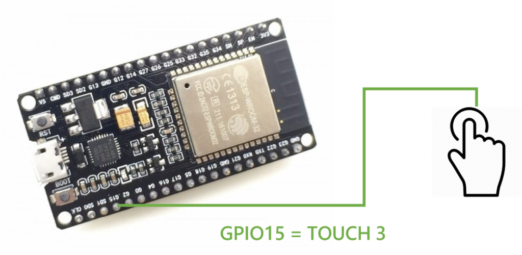
示意圖
要測試此範例,請將電路連接到通用輸入輸出接口 15,如下圖所示。
測試範例
將程式碼上傳到您的 ESP32,並以 115200 的鮑率打開序列埠監控視窗。

ESP32 進入深度睡眠模式。
您可以通過觸摸連接到 Touch Pin 3 的電線將其喚醒。
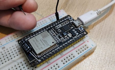
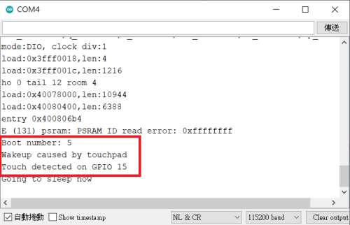
當您觸摸該引腳時,ESP32 會在序列埠監控視窗上顯示:啟動號、喚醒原因以及檢測到 GPIO 觸摸的位置。
外部喚醒
除了定時器和触摸引腳外,我們還可以通過切換引腳上的信號值來將 ESP32 從深度睡眠中喚醒,例如按下按鈕。這稱為外部喚醒。您有兩種外部喚醒的可能性:ext0 和 ext1。
外部喚醒 (ext0)
此喚醒源允許您使用引腳喚醒 ESP32。
ext0 喚醒源選項使用 RTC GPIO 喚醒。因此,如果請求此喚醒源,RTC 外設將在深度睡眠期間保持開啟。
要使用此喚醒源,請使用以下函數:
esp_sleep_enable_ext0_wakeup(GPIO_NUM_X, level)此函數接受您要使用的引腳作為第一個參數,格式為GPIO_NUM_X,其中X表示該引腳的 GPIO 編號。
第二個變數,level, 可以是 1 或 0。這表示將觸發喚醒的 GPIO 的狀態。
注意:使用此喚醒源,您只能使用 RTC GPIO 引腳。
外部喚醒 (ext1)
此喚醒源允許您使用多個 RTC GPIO。您可以使用兩種不同的邏輯功能:
- 如果您選擇的任何引腳為高電平,來喚醒 ESP32;
- 如果您選擇的所有引腳均為低電平,來喚醒 ESP32。
此喚醒源由 RTC 控制器實現。因此,可以在此模式下關閉 RTC 外設和 RTC 存儲器。
要使用此喚醒源,請使用以下函數:
esp_sleep_enable_ext1_wakeup(bitmask, mode)該函數接受兩個參數:
- 將導致喚醒的 GPIO 編號的位置碼;
- 模式:喚醒 ESP32 的邏輯。有可能:
- ESP_EXT1_WAKEUP_ALL_LOW:當所有 GPIO 變低時喚醒;
- ESP_EXT1_WAKEUP_ANY_HIGH:如果任何 GPIO 變高,則喚醒。
注意:使用此喚醒源,您只能使用 RTC GPIO 引腳。
程式碼
讓我們探索 ESP32 程式庫附帶的範例。轉到檔案>範例> ESP32 >DeepSleep> ExternalWakeUp:
/*
Deep Sleep with External Wake Up
=====================================
This code displays how to use deep sleep with
an external trigger as a wake up source and how
to store data in RTC memory to use it over reboots

This code is under Public Domain License.

Hardware Connections
======================
Push Button to GPIO 33 pulled down with a 10K Ohm
resistor

NOTE:
======
Only RTC IO can be used as a source for external wake
source. They are pins: 0,2,4,12-15,25-27,32-39.

Author:
Pranav Cherukupalli <cherukupallip@gmail.com>
*/

#define BUTTON_PIN_BITMASK 0x200000000 // 2^33 in hex

RTC_DATA_ATTR int bootCount = 0;

/*
Method to print the reason by which ESP32
has been awaken from sleep
*/
void print_wakeup_reason(){
  esp_sleep_wakeup_cause_t wakeup_reason;

  wakeup_reason = esp_sleep_get_wakeup_cause();

  switch(wakeup_reason)
  {
    case ESP_SLEEP_WAKEUP_EXT0 : Serial.println("Wakeup caused by external signal using RTC_IO"); break;
    case ESP_SLEEP_WAKEUP_EXT1 : Serial.println("Wakeup caused by external signal using RTC_CNTL"); break;
    case ESP_SLEEP_WAKEUP_TIMER : Serial.println("Wakeup caused by timer"); break;
    case ESP_SLEEP_WAKEUP_TOUCHPAD : Serial.println("Wakeup caused by touchpad"); break;
    case ESP_SLEEP_WAKEUP_ULP : Serial.println("Wakeup caused by ULP program"); break;
    default : Serial.printf("Wakeup was not caused by deep sleep: %d\n",wakeup_reason); break;
  }
}

void setup(){
  Serial.begin(115200);
  delay(1000); //Take some time to open up the Serial Monitor

  //Increment boot number and print it every reboot
  ++bootCount;
  Serial.println("Boot number: " + String(bootCount));

  //Print the wakeup reason for ESP32
  print_wakeup_reason();

  /*
  First we configure the wake up source
  We set our ESP32 to wake up for an external trigger.
  There are two types for ESP32, ext0 and ext1 .
  ext0 uses RTC_IO to wakeup thus requires RTC peripherals
  to be on while ext1 uses RTC Controller so doesnt need
  peripherals to be powered on.
  Note that using internal pullups/pulldowns also requires
  RTC peripherals to be turned on.
  */
  esp_sleep_enable_ext0_wakeup(GPIO_NUM_33,1); //1 = High, 0 = Low

  //If you were to use ext1, you would use it like
  //esp_sleep_enable_ext1_wakeup(BUTTON_PIN_BITMASK,ESP_EXT1_WAKEUP_ANY_HIGH);

  //Go to sleep now
  Serial.println("Going to sleep now");
  delay(1000);
  esp_deep_sleep_start();
  Serial.println("This will never be printed");
}

void loop(){
  //This is not going to be called
}
此範例在您觸發時喚醒 ESP32通用輸入輸出接口 33到高電平。程式碼範例顯示如何使用這兩種方法:ext0 和 ext1。如果您按原範例上傳代碼,您將使用 ext0。註釋了使用 ext1 的函數。我們將向您展示這兩種方法的工作原理以及如何使用它們。
這段程式碼與本文前面的程式碼非常相似。在裡面setup(),您首先初始化序列埠通信:
Serial.begin(115200);
delay(1000); //Take some time to open up the Serial Monitor然後,您將變數bootCount加1,並在序列埠監控視窗中列印該變量。
++bootCount;
Serial.println("Boot number: " + String(bootCount));接下來,您使用print_wakeup_reason()前面定義的函數。
//Print the wakeup reason for ESP32
print_wakeup_reason();在此之後,您需要啟用喚醒源。我們將分別測試每個喚醒源 ext0 和 ext1。
ext0
在本例中,ESP32 在通用輸入輸出接口 33被觸發為高電平:
esp_sleep_enable_ext0_wakeup(GPIO_NUM_33,1); //1 = High, 0 = Low代替通用輸入輸出接口 33,您可以使用任何其他 RTC GPIO 引腳。
示意圖
要測試此範例,請按照下面示意圖將按鈕連接到 ESP32。按鈕連接到通用輸入輸出接口 33使用下拉 10K 歐姆電阻。
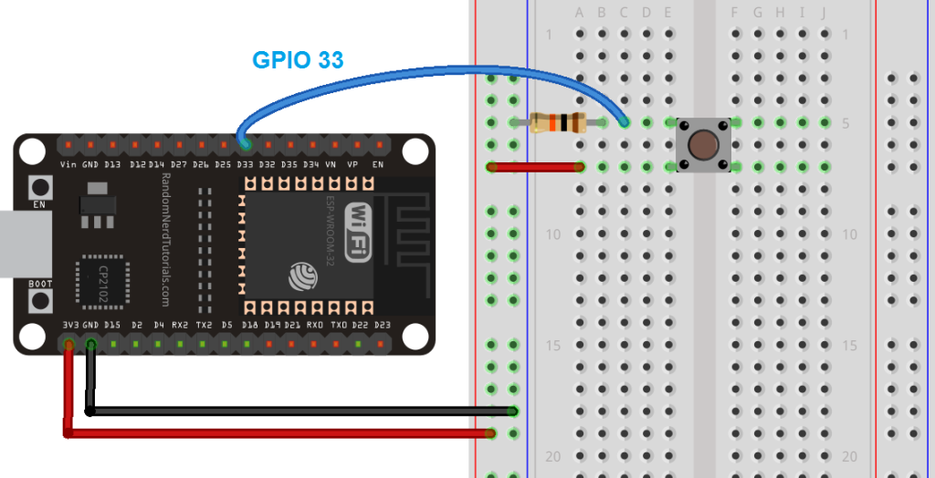
(此原理圖使用帶有 30 個 GPIO 的 ESP32 DEVKIT V1 模塊版本 – 如果您使用其他型號,請檢查您正在使用的板的引腳排列。)
注意:只有 RTC GPIO 可以用作喚醒源。除了 GPIO 33,您還可以使用任何 RTC GPIO 引腳來連接您的按鈕。
測試範例
讓我們測試這個例子。將範例程式碼上傳到您的 ESP32。確保您選擇了正確的開發和 COM 端口。以 115200 的鮑率打開序列埠監控視窗。

按下按鈕喚醒 ESP32。
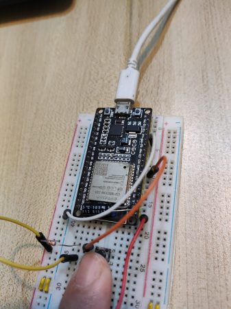
多試幾次,看到每次按下按鈕時啟動計數都會增加。
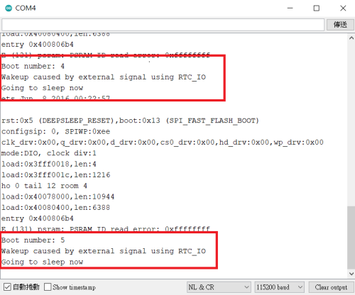
使用此方法可用於使用按鈕喚醒 ESP32,例如執行特定任務。但是,使用這種方法,您只能使用一個 GPIO 作為喚醒源。
如果你想擁有不同的按鈕,它們都喚醒 ESP,但執行不同的任務怎麼辦?為此,您需要使用 ext1 方法。
ext1
ext1 允許您使用不同的按鈕喚醒 ESP,並根據您按下的按鈕執行不同的任務。
而不是使用esp_sleep_enable_ext0_wakeup()功能,您使用esp_sleep_enable_ext1_wakeup()功能。在代碼中,對該函數進行了註釋:
//If you were to use ext1, you would use it like
//esp_sleep_enable_ext1_wakeup(BUTTON_PIN_BITMASK,ESP_EXT1_WAKEUP_ANY_HIGH);
取消註釋該函數,以便您擁有:
esp_sleep_enable_ext1_wakeup(BUTTON_PIN_BITMASK,ESP_EXT1_WAKEUP_ANY_HIGH);
該函數的第一個參數是您將用作喚醒源的 GPIO 的位置碼,第二個參數定義喚醒 ESP32 的邏輯。
在這個例子中,我們使用變量BUTTON_PIN_BITMASK,這是在程式碼開頭定義的:
#define BUTTON_PIN_BITMASK 0x200000000 // 2^33 in hex
這只是將一個引腳定義為喚醒源,通用輸入輸出接口 33. 您需要修改位元遮罩以將更多 GPIO 配置為喚醒源。
GPIO 位元遮罩
要獲取 GPIO 位元遮罩,請執行以下步驟:
- 計算 2^(GPIO_NUMBER)。以十進位儲存結果;
- 將十進位數轉換為十六進位;
- 替換您在BUTTON_PIN_BITMASK變數值。
單個 GPIO 的位元遮罩
為了讓您了解如何獲取 GPIO 位元遮罩,我們來看一個範例。在程式庫中的程式碼中,按鈕連接到通用輸入輸出接口 33. 為了得到遮罩通用輸入輸出接口 33:
1. 計算 2^33。你應該得到 8589934592;
2. 將該數字 (8589934592) 轉換為十六進制。你可以去這個轉換器來做到這一點:
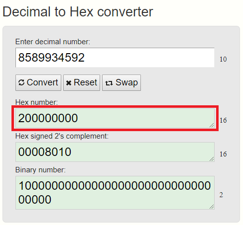
3.將十六進位數複製到BUTTON_PIN_BITMASK變量,你應該得到:
#define BUTTON_PIN_BITMASK 0x200000000 // 2^33 in hex
多個 GPIO 的位元遮罩
如果你想使用通用輸入輸出接口 2和通用輸入輸出接口 15作為喚醒源,您應該執行以下操作:
- 計算 2^2 + 2^15。你應該得到 32772
- 將該數字轉換為十六進位。你應該得到:8004
- 在BUTTON_PIN_BITMASK如下:
#define BUTTON_PIN_BITMASK 0x8004
識別用作喚醒源的 GPIO
當您使用多個引腳喚醒 ESP32 時,了解哪個引腳導致喚醒很有用。為此,您可以使用以下功能:
esp_sleep_get_ext1_wakeup_status()
此函數返回一個以 2 為底的數字,GPIO 編號為指數:2^(GPIO)。因此,要獲得十進位的 GPIO,您需要進行以下計算:
GPIO = log(RETURNED_VALUE)/log(2)
外部喚醒 – 多個 GPIO
現在,您應該能夠使用不同的按鈕喚醒 ESP32,並確定是哪個按鈕導致了喚醒。在這個例子中,我們將使用通用輸入輸出接口 2和通用輸入輸出接口 15作為喚醒源。
示意圖
將兩個按鈕連接到您的 ESP32。在這個例子中,我們使用通用輸入輸出接口 2和通用輸入輸出接口 15,但您可以將按鈕連接到任何 RTC GPIO。
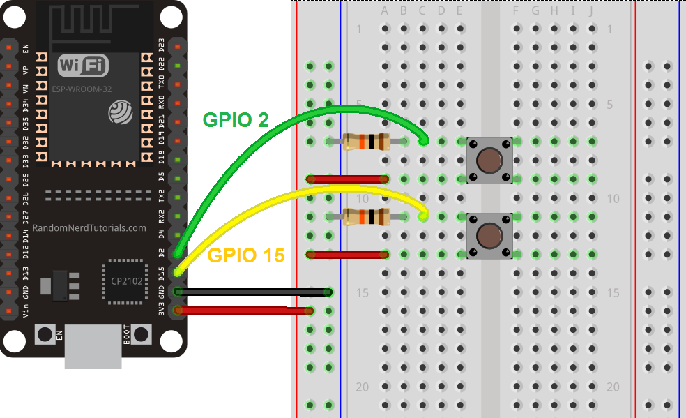
程式碼
您需要對我們之前使用的範例程式碼進行一些修改:
- 建立要使用的位元遮罩通用輸入輸出接口 15和通用輸入輸出接口 2. 我們之前已經向您展示如何執行此操作;
- 啟用 ext1 作為喚醒源;
- 使用esp_sleep_get_ext1_wakeup_status()函數來獲取觸發喚醒的 GPIO。
下一個草稿碼實現了所有這些更改。
/*
Deep Sleep with External Wake Up
=====================================
This code displays how to use deep sleep with
an external trigger as a wake up source and how
to store data in RTC memory to use it over reboots

This code is under Public Domain License.

Hardware Connections
======================
Push Button to GPIO 33 pulled down with a 10K Ohm
resistor

NOTE:
======
Only RTC IO can be used as a source for external wake
source. They are pins: 0,2,4,12-15,25-27,32-39.

Author:
Pranav Cherukupalli <cherukupallip@gmail.com>
*/

#define BUTTON_PIN_BITMASK 0x8004 // GPIOs 2 and 15

RTC_DATA_ATTR int bootCount = 0;

/*
Method to print the reason by which ESP32
has been awaken from sleep
*/
void print_wakeup_reason(){
  esp_sleep_wakeup_cause_t wakeup_reason;

  wakeup_reason = esp_sleep_get_wakeup_cause();

  switch(wakeup_reason)
  {
    case ESP_SLEEP_WAKEUP_EXT0 : Serial.println("Wakeup caused by external signal using RTC_IO"); break;
    case ESP_SLEEP_WAKEUP_EXT1 : Serial.println("Wakeup caused by external signal using RTC_CNTL"); break;
    case ESP_SLEEP_WAKEUP_TIMER : Serial.println("Wakeup caused by timer"); break;
    case ESP_SLEEP_WAKEUP_TOUCHPAD : Serial.println("Wakeup caused by touchpad"); break;
    case ESP_SLEEP_WAKEUP_ULP : Serial.println("Wakeup caused by ULP program"); break;
    default : Serial.printf("Wakeup was not caused by deep sleep: %d\n",wakeup_reason); break;
  }
}

/*
Method to print the GPIO that triggered the wakeup
*/
void print_GPIO_wake_up(){
  uint64_t GPIO_reason = esp_sleep_get_ext1_wakeup_status();
  Serial.print("GPIO that triggered the wake up: GPIO ");
  Serial.println((log(GPIO_reason))/log(2), 0);
}

void setup(){
  Serial.begin(115200);
  delay(1000); //Take some time to open up the Serial Monitor

  //Increment boot number and print it every reboot
  ++bootCount;
  Serial.println("Boot number: " + String(bootCount));

  //Print the wakeup reason for ESP32
  print_wakeup_reason();

  //Print the GPIO used to wake up
  print_GPIO_wake_up();

  /*
  First we configure the wake up source
  We set our ESP32 to wake up for an external trigger.
  There are two types for ESP32, ext0 and ext1 .
  ext0 uses RTC_IO to wakeup thus requires RTC peripherals
  to be on while ext1 uses RTC Controller so doesnt need
  peripherals to be powered on.
  Note that using internal pullups/pulldowns also requires
  RTC peripherals to be turned on.
  */
  //esp_deep_sleep_enable_ext0_wakeup(GPIO_NUM_15,1); //1 = High, 0 = Low

  //If you were to use ext1, you would use it like
  esp_sleep_enable_ext1_wakeup(BUTTON_PIN_BITMASK,ESP_EXT1_WAKEUP_ANY_HIGH);

  //Go to sleep now
  Serial.println("Going to sleep now");
  delay(1000);
  esp_deep_sleep_start();
  Serial.println("This will never be printed");
}

void loop(){
  //This is not going to be called
}
您在程式碼開頭定義了 GPIO 位元遮罩:
#define BUTTON_PIN_BITMASK 0x8004 // GPIOs 2 and 15
您建立一個函數來列印導致喚醒的 GPIO:
void print_GPIO_wake_up(){
 int GPIO_reason = esp_sleep_get_ext1_wakeup_status();
 Serial.print("GPIO that triggered the wake up: GPIO ");
 Serial.println((log(GPIO_reason))/log(2), 0);
}
最後,啟用 ext1 作為喚醒源:
esp_sleep_enable_ext1_wakeup(BUTTON_PIN_BITMASK,ESP_EXT1_WAKEUP_ANY_HIGH);
測試草稿碼
有兩個按鈕連接到通用輸入輸出接口 2和通用輸入輸出接口 15,您可以上傳提供給您的 ESP32 的程式碼。確保您選擇了正確的開毃板和 COM 端口。
ESP32 現在處於深度睡眠模式。您可以通過按下按鈕將其喚醒。
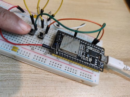
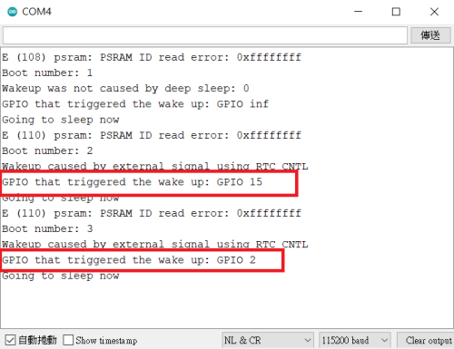
以 115200 的鮑率打開序列埠監控視窗。按下按鈕喚醒 ESP32。
你應該在序列埠監控視窗上得到類似的東西。
總結
在本課程中,我們向您展示如何使用 ESP32 進行深度睡眠以及喚醒它的不同方法。您可以使用定時器、觸摸引腳或 GPIO 狀態的更改來喚醒 ESP32。
讓我們總結一下我們對每個喚醒源的了解:
定時器喚醒
- 要啟用定時器喚醒,您可以使用esp_sleep_enable_timer_wakeup(time_in_us)功能;
- 使用esp_deep_sleep_start()開始深度睡眠的功能。
觸摸喚醒
- 要將觸摸引腳用作喚醒源,首先,您需要使用以下方法將中斷附加到觸摸引腳:touchAttachInterrupt(Touchpin,callback,Threshold)
- 然後,您可以使用以下命令啟用觸摸引腳作為喚醒源:esp_sleep_enable_touchpad_wakeup()
- 最後,您使用esp_deep_sleep_start()使 ESP32 進入深度睡眠模式的功能。
外部喚醒
- 您只能將 RTC GPIO 用作外部喚醒;
- 您可以使用兩種不同的方法:ext0 和 ext1;
- ext0 允許您使用單個 GPIO 引腳喚醒 ESP32;
- ext1 允許您使用多個 GPIO 引腳喚醒 ESP32。
我們希望您發現本指南對您有用。

